Wires Wires Everywhere
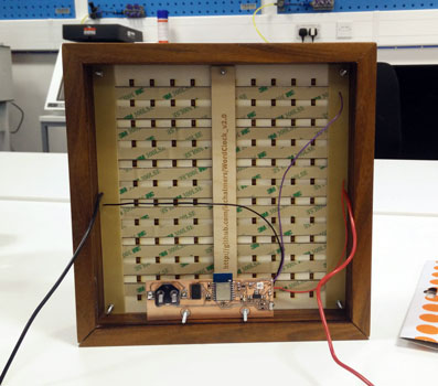
This is what the inside of WordClock1.0 looked like:
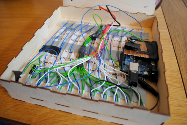
It took forever to wire all the LEDs, and the duct tape/glue to hold them in place was a mess. To make life easier for myself, I set about designing some power and signal distribution boards.
Power Distribution Boards
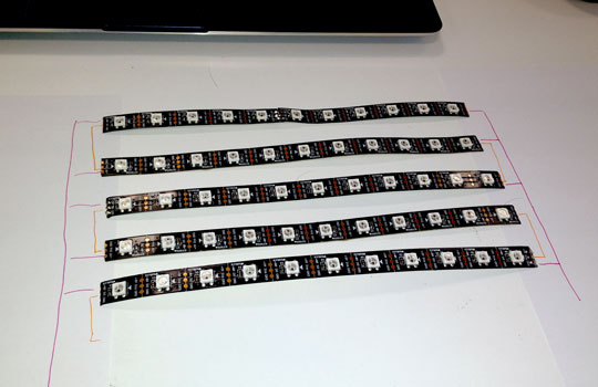
As a quick sanity check, I did a trace layout on paper with some of the LED strips.
After that, it was back to KiCAD. I made sure to layout the schematic in such a way that it pretty much translated directly to the PCB layout.
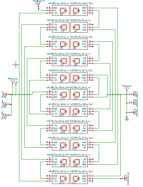
What's nice about the design is that it's symmetrical: you can just cut two of the same board and use one for power and one for ground.

As always, I printed the PCB out on paper first and made sure it looked sensible using the cardboard word clock. The eagle eyed amongst you will notice that the paper print out in the photo below doesn't have the mounting holes. Spotting that mistake on paper saved me a lot of time!
One other minor mistake was that I forgot to add a footprint for adding a nice big 1000µF capacitor as a local power source for the LEDs. Luckily I don't seem to need it, but I've already updated the PCB to have a space for one just in case.
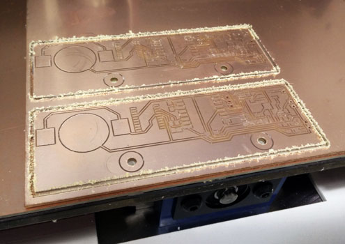
Happy with the design, I milled a pair of boards on the Denford. This is a board that really shows how great the Denford is compared to the Modela. Not only would the board not have fit on the Modela bed, but I imagine that doing a board this long would be a nightmare for getting a consistent cut depth on the copper. Yay for floating heads!
With the boards milled, I started soldering the LED strips onto the boards, checking that everything was working every couple of strands.
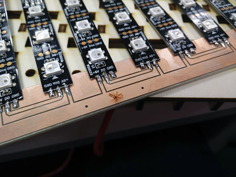
An added benefit of the power distribution boards is that they also act as clamps that hold the LEDs in place. That's two problems fixed with one elegant solution!
Cutting Another Control PCB
It was at this point that I had a better idea of where I wanted to mount the control PCB, so I cut a couple of new boards that had mounting holes in the right place.
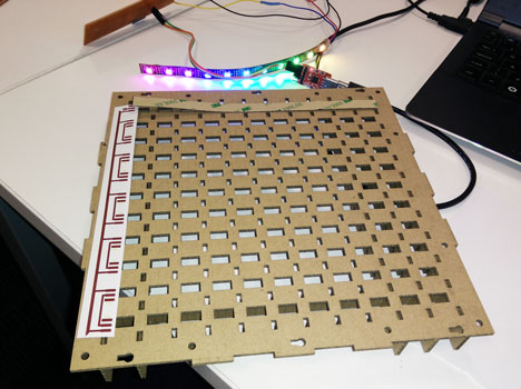
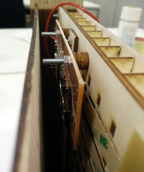
Before soldering everything up, I did a dry-run and made sure that everything fit together properly.
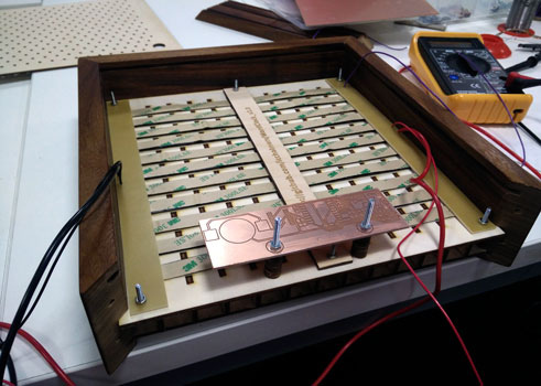
In it's current iteration, I have to use some stand-offs to mount the control PCB above the central support strip. In the near future (but after Fab Academy is finished), I plan on getting rid of the central support in favour of two supports that would line up with the mounting holes on the PCB. That would save me a nut and a bolt, and also mean I could make the clock thinner. The chunky version is cool for a free standing clock, but a thinner one could potentially be wall mounted.
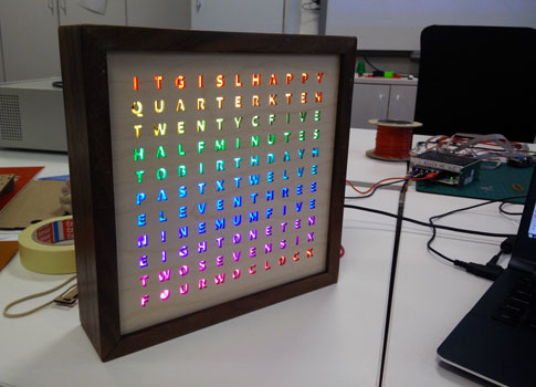
Happy with the design for the moment, I soldered up one of the new boards and had my first real look at what the interior of the clock would look like.
I hope we can all agree that that is a HELL of a lot better than v1.0!
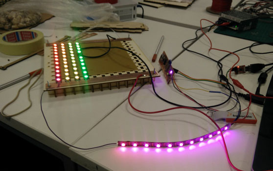
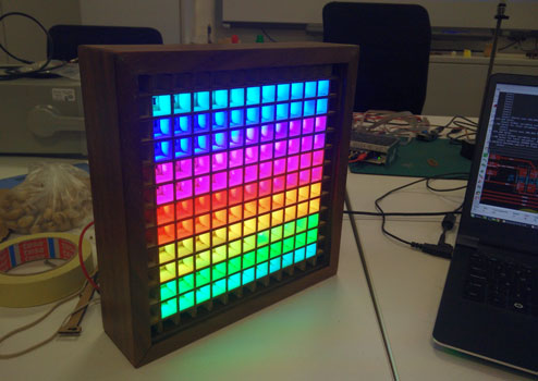
Pretty Pattern Testing
With the hardware basically finished, I extended my rainbow test pattern sketch to use all 122 LEDs. It looks pretty funky if I do say so myself!
Hardware is hard and software is easy, right?! Well I guess there's only one way to find out - go check out the next update: Update 4: Software and Leaking Light.
Comments
comments powered by Disqus