This Week's Assignment
The assignment for this week was to make a FabISP board. ISP stands for In-circuit Serial Programmer i.e. the device can program chips that are already integrated into their target circuit. The programmer targets Atmel's 8-bit AVR range of microcontrollers such as the ATtiny45 and the ATmega328 found on the Arduino Uno.
This is the final outcome:

Choosing A FabISP Design
There are a number of variations on the FabISP floating around the internet. All of them are based on Dick Streefland's USBTiny code, which implements USB in software on ATtinys.
From there, the lineage seems to be (roughly), from oldest to newest:
-
Dick Streefland's USBtiny SPI converter: This was the first application Dick wrote that used USBtiny.
-
Lady Ada's USBtinyISP: Lady Ada made some low level software changes and made it "official" by adding USB VID/PIDs, as well as some hardware changes.
-
David Mellis's FabISP: David started with the USBtinyISP as a reference but the finished product is almost completely different. He swapped all of the through hole components for SMD ones. I think most (if not all) of the parts are standard in the Fab Lab inventory.
-
Andy Bardagjy's FabISPkey: The biggest change Andy made was to swap the USB Mini socket for a PCB based USB plug. He also made a variant designed for targeting lower voltage microcontrollers.
-
Valentin Heun's FabISP: Valentin tweaked Andy's layout so that after the initial programming of the ATtiny, a section of the board could be snapped off. This meant no more desoldering of jumper wires and it made if obvious that the USB would not function until the ATtiny had been programmed.
-
Zaerc's FabTinyStar: AKA the FabTiny*. Version 0.3 "Bas" is the most common variant. This board is a real evolution of the original design. It uses the smaller ATtiny45 in place of the ATtiny44, which has two big advantages. The first is that it's smaller (8 pins vs 14). The second is that with some clever software teaks to calibrate the internal RC oscillator, it can be used without an external crystal. On top of that, the FabTiny* also adds a reset button and a board edge switch for selectively applying power to the target board.
I decided to make the FabTiny*, as it had more features and had an overall more elegant design. I'm not a fan of board edge USB connectors though, as I tend to find them a bit picky about making a good connection. Perhaps I'll make my own variation in the upcoming weeks...
I followed the FabTiny* Tutorial in the class archive.
Milling On The Modela
I re-milled a new acrylic sacrificial layer for general use on the Modela and then set up two pieces of FR1 (or it might actually be FR2 - we're not sure!). One as a sacrifice, one for milling the actual board.
I was a little apprehensive about using the Modela. Our lab has always had trouble with the machine, probably due to some issues with the serial cable. The milling job would start out fine, and then suddenly the machine would go crazy. Luckily, recent updates to the Fab Modules seem to have taken care of that problem.
The second issue was getting the appropriate bits. We had two micro milling bits in the lab: a 0.4mm micromill and a (0.1mm?) V-shaped engraving bit. Unfortunately, neither is quite the right sized shaft for the collet on the Modela. Our lab manager Graham managed to jimmy some filling in the gaps for the V-bit and get it centred pretty well, but it did mean that we couldn't loosen the bit in the collet to drop it onto the surface of the copper. It's pretty easy to set the zero point just by jogging the bit using the controls on the front of the machine though.

I used the Fab Modules installed on my laptop (running Linux Mint 17.1 from an external hard drive). I decided to start off trying the V-shaped engraving bit, since it had been centred in the collet and the 0.4mm bit hadn't. With the cut path generated, a z cut depth of -0.15 and a feedrate of 3mm/s, I sent the file to the Modela.
It was obvious pretty quickly that the bit wasn't going deep enough.

I stopped the job, reset the model, increased the cut depth to -0.2mm and restarted the job.

The white powder was a good indication that I was getting all the way through the copper to the FR1 underneath.
I let the job run to completion, and then decided to try the 0.4mm bit, even though the shaft of the bit was ever-so-slightly too small for the Model (by fractions of a millimetre).

The top board was done with the 0.4mm bit, and the bottom one with the V-shaped engraving bit. When you're working with bits that are fractions of a millimetre wide, any play in the collet just gets magnified. The top board was certainly usable (although the traces looked a little on the thin side) but the V-shaped bit used for the bottom board gave a cleaner result.
Of the two, I decided it was worth cutting out the bottom board.

Woops. I was cutting with the default settings in the Fab Modules, and the 0.8mm bit broke almost instantly. I'm not sure it's the same bit as recommend in the Inventory - our ones seem to be quite a bit longer than the ones I've seen in other peoples pictures of the process. With such a long cutting shaft, in hindsight it's not surprising that the bit broke.
With a new bit in place, I reduced the feedrate from 4mm/s to 1mm/s, and reduced the cut depth per pass from 0.6mm to 0.3mm (or at least, I thought I had... More on that later).

I pretty much held my breath for the entire job, but in the end it finished without incident.


I now had a board, but I wasn't particularly happy with it. Feeling like I was starting to get the hang of it, I decided to try a few more milling jobs with the V-shaped bit at different settings and compare the results.
The first one increasing the feedrate to 4mm/s. The job finished, and it looked pretty good. What I didn't realise was that my laptop had died right at the end of the job. I pushed the view button to go back and start the next job, and apparently in it's death throws my laptop sent some junk to the serial port and this happened...

The bit went back to it's last cut point, plunged to the cut depth and then proceeded to go to it's home position... Fair to say that I swore quite a lot, and the bit never survived its ordeal.
If it hadn't been for the giant gouge through the middle of the board, I would have been pretty happy with that one. As it was, I had space for two more attempts. I tried one at 2mm/s feed rate, but the board must have been a bit unlevel and part of the circuit never cut (the front board in the image below, near the top of the board). I decided that the best result had been with the 4mm/s feed rate, so re-ran the job that had been destroyed.
It finished fine and the board looked good so I started the board cut out. Then this happened...

I was starting to feel pretty guilty at this point. For those who have lost count, I had broken three bits by this point. I thought that 1mm/s and a cut depth of 0.3mm/s would have been OK, but no. Turns out the last job finishing was a bit of a fluke. I examined the board, and was confused to see that the cut depth was definitely more than 0.3mm.
Now that I've had some time to reflect, I think I know my mistake. Turns out I had missed a setting...

Yup, the first cut was ALWAYS 0.6mm, regardless of what I had been setting the cut depth to. To be honest it's a miracle I only broke two bits. At least I'll have plenty of opportunities to try again as the weeks go on!
I was a nervous wreck by this point. With a new bit in, I ran the cut job at 0.5mm/s with a cut depth of 0.2mm. It took ages but as long as I didn't break another bit, I didn't care. Since I still had the initial cut depth set to 0.6mm, I was lucky I didn't break bit number four.

See that thin bit of copper around the USB connector? I'm taking that as proof that I hadn't been imagining that I could actually see the bit bending as the board was cut out. The (possibly imagined) bend meant that the board outline was slightly off, and the board ended up a little larger than intended. It was easy to scrape off the copper with a craft knife, but I did have to file down the edges of the USB so that it would fit in a USB port.
Anyway, a wash and some light sanding later, I was ready for the easy part: soldering.
This was the first time I had soldered on a PCB like this one, and the first time I had done any 1206 footprints (thats the package size for the resistors and the capacitors). I've got some soldering experience, but it's always been on nice PCBs from fab houses with helpful solder masks. I admit it's not the cleanest of solder jobs but I think that's partly due to the board design (I know, I know. Excuses, excuses). For my own boards I'll make sure that each component has a defined pad i.e. that it's not connecting to one giant copper plane. That should help the surface tension of the solder to pull the solder up around the components, instead of pooling out everywhere. That capacitor at the bottom left of the board is particularly embarrassing.
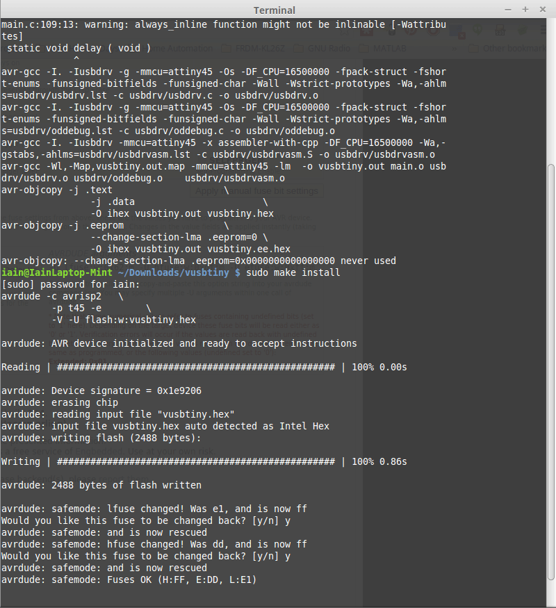
After another quick wash (and dry), it was time to program the board. I followed the instructions and everything pretty much worked straight off. I used the AVRISP mkII to do the programming. The only unexpected part was avrdude warning me that the fuses had changed (which didn't seem to happen in the screenshots from the tutorial). I checked that the new fuses bits were sensible and went ahead and ignored the warning (although notice that the screenshot below was from when I first chickened out and reset them!).
I then plugged the FabTiny* into my USB port, said a quick prayer and....

Success! The device was recognised as "Multiple Vendors USBtiny" (second line from the bottom).
Happy that everything was working, I blew the final fuse (so to speak) and the FabTiny* was finished.

Final Thoughts
Overall, I thought the whole process was a bit of a kerfuffle. If you could 100% guarantee a board would come out perfect every time, it would probably be OK. But I think that's rarely the case. I would happily use the Modela for really small, simple circuits that I needed right now. For example, a little break out board for an SMD chip so that I could quickly test it in a breadboard (I disagree with Neil on breadboards. They're just another tool, and as long as you understand their limitations then they're pretty useful for prototyping).
Instead of milling, I would much rather just send out a board to somewhere like OSHPark. Sure, I might have to wait a few weeks, but during that time I can happily be doing something else. For almost the same price, I can get professional double sided boards with solder masks, silk screens and all the trimmings.
Comments
comments powered by Disqus